Author Archives:
Contour Adaptation
Flicker adaptation.
If you adapt to two squares, one black and one white, you can see two negative afterimages afterwards, They will be respectively white and black.
If you adapt to a square that flickers at 5-10Hz between black and white (on a grey surround), then afterwards there will be no visible afterimage.But there will be a patch of reduced sensitivity; a test patch will look reduced in apparent contrast.
Contour adaptation.
If you adapt to a flickering outline circle and then view a congruent low-contrast grey disk, the whole disk will be apparently halved in contrast; and may even become invisible. This suggests that brightness is coded at edges!
Contour adaptation does not work for colored patches, and it does not transfer from one eye to the other. This suggests that it is a low-level process in the Magnocellular pathways.
There are 6 stars here, 3 light and 3 dark. Fixate the red spot and adapt to the solid flickering stars (above) and flickering outlines (below). All six stars reappear, but you see only four of them. The outlines are as effective adaptors as the solid flickering stars.
[quicktime width=”600″ height=”400″]http://quote.ucsd.edu/anstislab/files/2012/11/fourdisk.mov[/quicktime]
As in the previous movie, adapting to the flickering outline circles makes the test disks disappear from view. Adapting circles flicker at 1, 2, and 4 Hz, and the rotating dashed circle is also an effective adaptor; clearly flicker rate is not crucial.
[quicktime width=”600″ height=”400″]http://quote.ucsd.edu/anstislab/files/2012/11/StarBurst1.mov[/quicktime]
Selective adaptation. Fixate each red spot in turn (4 experiments). Adapting to the external outlines (top row) makes these outlines disappear, leaving only disembodied quadrants. Adapting to the internal crosses (bottom row) makes each star look like a uniform gray.
[quicktime width=”600″ height=”400″]http://quote.ucsd.edu/anstislab/files/2012/11/Kanisza.mov[/quicktime]
Left: You can’t adapt out the subjective contours of a Kanisza square. But right, you can adapt out the objective L-shaped corners: now the subjective square looks like a foggy blob or luminous haze.
[quicktime width=”600″ height=”400″]http://quote.ucsd.edu/anstislab/files/2012/11/7_PyramidAdapt3.mov[/quicktime]
While focusing on the central spot, view the flickering contours that superimpose onto the edges of the dark (left) and light (right) pyramids. During the test period, the pyramids now appear to have the same luminance as the background. Copies if the central dark and light square are presented above the pyramids for the sake of comparison.
[quicktime width=”600″ height=”400″]http://quote.ucsd.edu/anstislab/files/2012/11/5_HalfMoon.mov[/quicktime]
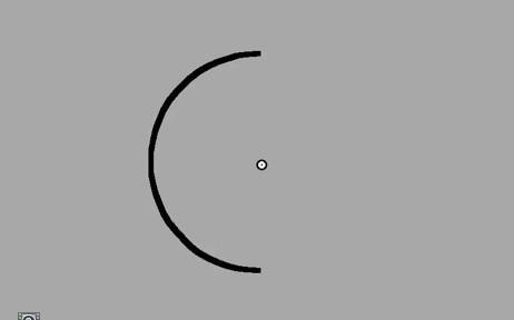
First adapt to the flicker of the semicircle, presented superimposed on the left edge of the disk. Following flicker adaptation, not only has the left edge of the disk disappeared, but also a brightness gradient is apparent, making the disk appear like a half moon. In the absence of edge information on the left half of the disk, the brain appears to interpolate the brightness levels from the unadapted right edge to the background level.
[quicktime width=”600″ height=”400″]http://quote.ucsd.edu/anstislab/files/2012/11/9_PopoutDisk.mov[/quicktime]
This demonstration shows a test field of seven randomly arranged low-contrast annuli. All the annuli have the same size and shape so none of them pops out. But now adapt to the set of flickering circles, maintaining strict fixation on the small white square. When the test annuli re-appear, you will notice that one of them seems to have turned into a solid disk, which pops-out from the background annuli.
A flickering outline contour is a much more effective adaptor than a flickering blurred surface. Gaze at the center spot and view the flickering adapting stimuli, on the left an outline ring and on the right a blurred surface. Following adaptation, the left test disk disappears while the right disk remains visible. Adapting to the flickering contour leads to contour erasure, while adapting to the surface does not. Conclusion: Brightness is coded at edges. …..IF you adapt to the outline circle on the left, and the co
 mplete blurred disk on the right, only the former has an aftereffect. Contours rule!
An adapting half-circle makes the test disk look graded…
Incomplete contour erasure can affect the perceived brightness of a uniformly filled light grey disk. First adapt to the flicker of the semicircle, presented superimposed on the left edge of the disk. Following flicker adaptation, not only has the left edge of the disk disappeared, but also a brightness gradient is apparent, making the disk appear like a half moon. In the absence of edge information on the left half of the disk, the brain appears to interpolate the brightness levels from the unadapted right edge to the background level.Incomplete contour erasure can affect the perceived brightness of a uniformly filled light grey disk. First adapt to the flicker of the semicircle, presented superimposed on the left edge of the disk. Following flicker adaptation, not only has the left edge of the disk disappeared, but also a brightness gradient is apparent, making the disk appear like a half moon. In the absence of edge information on the left half of the disk, the brain appears to interpolate the brightness levels from the unadapted right edge to the background level.

Laughing photo
illusory window (pending draft)
https://anstislab.ucsd.edu/files/2014/10/Hummingbird_DotsSine.mov
What you see in the movie is two striped disks moving bodily in one direction. Stripes are painted, stuck to the disks. On static background (upper field), what you see is what you get. But on flickering background (lower field), stripes now move much faster than the disk, overtaking it! Stripes are no longer stuck to the disks but drifting within a circular window. Illusion is stronger in peripheral vision; but you can see some of it even when you’re tracking the disks with your eyes.
[quicktime width=”600″ height=”400″]https://anstislab.ucsd.edu/files/2014/10/Hummingbird_DotsSine.mov[/quicktime]
Patterns don’t matter – random dots and sinusoidal gratings also give the same effect.
[quicktime width=”600″ height=”400″]https://anstislab.ucsd.edu/files/2014/10/Movie2.mov[/quicktime]
You can measure the strength of the illusion in this movie. Within each window, grating moves at 25%, 50%, 75%, 100% of the window speed (from top to bottom). Since on a flickering background (right), it makes the gratings move much faster than their windows, they look quite different from their corresponding windows on the left (control conditions). For most observers, the gratings appear locked to the windows labelled 25% or 50%.
[quicktime width=”600″ height=”400″]https://anstislab.ucsd.edu/files/2014/10/Hummingbird_RingWith-out.mov[/quicktime]
While gray contour around the window enhances the illusion, you can still see it without the contour (at least in some cases).
We think this is due to reversed-phi illusion – windows lag behind because of reversed-phi, making gratings appear relatively faster.
[quicktime width=”600″ height=”400″]https://anstislab.ucsd.edu/files/2014/10/Hummingbird_color.mov[/quicktime]
To see reversed-phi motion, target (in this case, window) has to change its polarity, i.e. being lighter or darker than its background. So, if we replace the background flicker with color flicker with minimal luminance change, the illusion disappears.
[quicktime width=”600″ height=”400″]https://anstislab.ucsd.edu/files/2014/10/Movie3_AnstisKaneko.mov[/quicktime]
For the same reason, if we replace the gray contour with black contour, the illusion disappears.
[quicktime width=”600″ height=”400″]https://anstislab.ucsd.edu/files/2014/10/Hummingbird_Lowcont.mov[/quicktime]
this only applies to WITHOUT-gray-ring stimuli; when background flicker has very low contrast, the illusion disappears, again. But lowering contrast of the grating does almost the opposite, enhances the illusion.
[notes for us: yes, this should only apply to without-ring condition, assuming reversed phi explains this illusion. But even with ring, low contrast background seems to reduce the illusion very much! How can this happen?]
[quicktime width=”600″ height=”400″]https://anstislab.ucsd.edu/files/2014/10/Movie4_AnstisKaneko.mov[/quicktime]
Illusory drifting within a window with Sae Kaneko
[quicktime width=”600″ height=”400″]https://anstislab.ucsd.edu/files/2014/10/Movie1.mov[/quicktime]
What you see in the movie is two striped disks moving bodily across the screen. The stripes are painted, stuck to the disks. On a static background (upper field), what you see is what you get. But on a flickering background (lower field), the stripes appear to move much faster than the disk, overtaking it! Stripes are no longer seen as stuck to the disks but seem to drift within a circular window. The illusion is stronger in peripheral vision; but you can see some of it even when you track the disks with your eyes.
[quicktime width=”600″ height=”400″]https://anstislab.ucsd.edu/files/2014/10/Hummingbird_DotsSine.mov[/quicktime]
Patterns don’t matter – random dots and sinusoidal gratings also give the same effect.
[quicktime width=”600″ height=”400″]https://anstislab.ucsd.edu/files/2014/10/Movie2.mov[/quicktime]
You can judge the strength of the illusion in this movie. Within each window, the grating moves at 25%, 50%, 75%, 100% of the window speed (from top to bottom). Since the flickering background (on the right) makes the gratings appear to move much faster than their windows, they look quite different from their corresponding windows on the left (control conditions). For most observers, the gratings appear locked to the windows labelled 25% or 50%. So the gratings appear to move 2x or 4x faster than their window.
[quicktime width=”600″ height=”400″]https://anstislab.ucsd.edu/files/2014/10/Hummingbird_RingWith-out.mov[/quicktime]
While a gray contour around the window enhances the illusion, you can still see it without the contour (at least in some cases).
We think this is due to reverse-phi illusion – windows lag behind because of reverse-phi, making gratings appear relatively faster.
[quicktime width=”600″ height=”400″]https://anstislab.ucsd.edu/files/2014/10/Hummingbird_color.mov[/quicktime]
To see reverse-phi motion, the target (in this case, window) has to change its polarity on each frame, i.e. being alternately lighter or darker than its background. So, if we replace the background flicker with color flicker with minimal luminance change, the illusion disappears.
[quicktime width=”600″ height=”400″]https://anstislab.ucsd.edu/files/2014/10/Movie3_AnstisKaneko.mov[/quicktime]
For the same reason, if we replace the gray contour with black contour, the illusion disappears.
[quicktime width=”600″ height=”400″]https://anstislab.ucsd.edu/files/2014/10/Hummingbird_Lowcont.mov[/quicktime]
this only applies to WITHOUT-gray-ring stimuli; when background flicker has very low contrast, the illusion disappears, again. But lowering contrast of the grating does almost the opposite, enhances the illusion.
[quicktime width=”600″ height=”400″]https://anstislab.ucsd.edu/files/2014/10/Movie4_AnstisKaneko.mov[/quicktime]
Moving Sawteeth
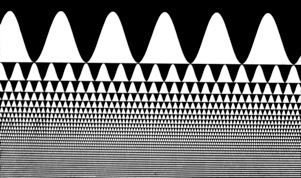
As the moving ramp waveforms move back and forth they appear to change in brightness. As they move to the right, the upper field seems to brighten (and look slightly yellow) and the lower field seems to dim (and look slightly blue). A fixed retinal receptor viewing the upper half will see continuous brightening ramps punctuated by sudden drops. Probably, visual nonlinearities reduced the effectiveness of the sudden drops, so the ramping brightness predominates. (Cavanagh & Anstis, Vision Research 1986)
When the stripes move steadily to the right, the upper field looks apparently brighter. Adapt for ~20s, then click the Pause button. You will see a leftward motion aftereffect, plus a ‘ramp aftereffect’ of apparent dimming in the upper half and apparent brightening in the lower half.
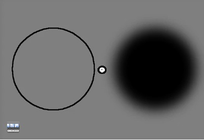
Blurred disc vs. Edges
 [quicktime]http://quote.ucsd.edu/anstislab/files/2013/10/BlurSharp1.mov[/quicktime]
A flickering contour is a much more effective adaptor than a flickering blurred surface. Gaze at the center spot and view the flickering adapting stimuli, on the left a ring and on the right a blurred surface. Following adaptation, the left test disk disappears while the right disk remains visible. Adapting to the flickering contour leads to contour erasure, while adaptating to the surface does not.
Half Moon Illusion
 [quicktime]http://quote.ucsd.edu/anstislab/files/2013/10/5_HalfMoon.mov[/quicktime]
Incomplete contour erasure can affect the perceived brightness of a uniformly filled light grey disk. First adapt to the flicker of the semicircle, presented superimposed on the left edge of the disk. Following flicker adaptation, not only has the left edge of the disk disappeared, but also a brightness gradient is apparent, making the disk appear like a half moon. In the absence of edge information on the left half of the disk, the brain appears to interpolate the brightness levels from the unadapted right edge to the background level.
Footsteps
Look at this movie (above). Both squares actually move smoothly side by side at a constant speed. But when a background of stationary swipes is turned one the stripes aper to move fas and slow in alternation, like the two feet of a walking person, (Actually they always maintain the same constant speed)
The blue and yellow squares move exactly in step. But when the background is striped they seem to speed up and slow down in alternation. Reason: when the leading & trailing edges of the dark blue square lie on the black stripes, their contrast is low so the motion looks slower (Pete Thompson 1976). On the white stripes the edges have high contrast so the motion seems to speed up. The opposite is true for the light yellow squares. Maybe this is like cars that appear to go slower in the fog.
Below: Same things, with more squares
(Below): Squares and stripes are now second-order, defined by contrast not luminance.
Footsteps illusion is still seen. (With AKIYOSHI KITAOKA)
(Below): Squares and stripes are still second-order, but now defined by grain size. Footsteps illusion is still seen. (With AKIYOSHI KITAOKA)
Reason: As the dark square hits a white vertical line and its horizontal motion speeds up, it also hits a black horizontal line and its vertical motion slows down. For the dark square, the top and bottom edges have high contrast, the left and right edges have low contrast, and so its vertical motion is exaggerated. For the light square, the opposite is true.
Rotating Rings with Patrick Cavanagh

 The texture filling the rings is either stationary (rings seem to move slowly) or moves in the opposite directions to the rings (rings slide over each other, each spinning CCW as the pair turn CW) or in the same direction as the rings (rings appear to move very fast as a rigid
The rings appear to slide over one another when the intersections are dark so that they obey Metelli’s transparency rules. They lock together into a rigid trefoil when the intersections are light and look opaque…..
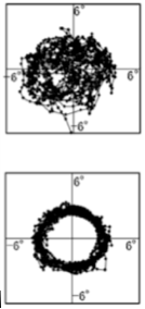
Left-hand rotating rings with painted-on spots were parsed as a solid figure of eight. Observers could easily track rigid intersection (lower right graph) (Anstis & Ito, Perception 2011).
Right-hand rotating rings with vertically aligned gaps or spots appeared to slide. Observers could not track sliding intersection where rings cross. Upper right-hand graph shows the noisy pattern of eye movements.
[quicktime width=”600″ height=”400″]http://quote.ucsd.edu/anstislab/files/2012/12/Rings2010_1.mov[/quicktime]<p>
Eye-movement tracked while watching the stimuli.
![]()

