Category Archives: Illusions

Dotty Lines

What’s the difference?

a:  the rightward motion of a simple black line can be decomposed into 2 vectors, along and across the line.
b: The vector along the line is not seen, so the line is perceived as moving at right angles to its own length.
c:  The rightward motion of a dotted line comprises the same two vectors. However, the black/white contrast along the line is much stronger than the second-order black/gray or white/gray contrast across the line.
d: So now the vector along the line is perceptually weighted more than the vector across the line.
Move a  pencil point slowly to left and right across the dots, and they will appear to move up and down.  Reason: Each pair of black/white dots contains oblique components.  This is a minimal version of Pinna’s expanding/ rotating diamond shapes.

Boogie Woogie Illusion

Boogie Woogie Illusion
with Patrick Cavanagh

Gaze at the two black fixation marks in turn.
Bottom left (control condition): The surround is darker than the drifting checkered lines, which are seen normally.
Top right: The surround luminance lies between the luminances of the spots (checkers) that constitute the lines. Now the spots appear to trickle non-rigidly along the lines, as though the spots are moving faster than the lines. Explanation: When the spot luminances straddle the surround luminance, the contrast along the lines (between adjacent spots) is higher than across the lines (between the surround and the spots). The motion with the higher contrast wins, and motion along the lines predominates over the sideways motion of the lines.

Cogwheels Motion

[quicktime width=”600″ height=”400″]http://anstislab.ucsd.edu/files/2012/11/cogs1-6_1.mov[/quicktime]
Movie #1: Silvanus P. Thompson, in “Light visible & invisible” (1897) noted that when a cogwheel pattern moves along a CW path, it shows an illusory counter-CW rotation. (I admit that these movies do not work all that well. Try jiggling a paper version.)
[quicktime width=”500″ height=”400″]http://anstislab.ucsd.edu/files/2012/11/cogs2-4.mov[/quicktime]
Movie #2: Low contrast cogs seem to rotate CW. I don’t know why.
[quicktime width=”500″ height=”400″]http://anstislab.ucsd.edu/files/2012/11/cogs3.mov[/quicktime]
Movie #3: Hedgehogs with outward-pointing teeth seem to rotate CW.
[quicktime width=”500″ height=”400″]http://anstislab.ucsd.edu/files/2012/11/cogs4-2.mov[/quicktime]
Movie #4: Simulation & explanation. When only the outer tips of hedgehog teeth are visible, they rotate strongly CW. When only the inner teeth of cogwhels are visible, they rotate strongly CCW.

Chopsticks Illusion

Each chopstick moves along a clockwise (CW) circular path.  their intersection also appears to move CW, although it really moves CCW.  Conclusion: The CW motion of the tips propagates along the lines to the central intersection. (To avoid interactions, look at each display in turn while covering the others with your hand.)

Similarly, the two black ring stiuli are the same except fo the small whute gaps.  Left: When the gaps float, always lying at ‘6 & 12 o’clock’, one perceives two rings circling each other.  Right: When the gaps rotate with the rings, one perceives a single rotating figure-8.  So local gaps control the global percept.

On the left: Try to track the central intersection of the chopsticks, or the X-junction where the rings intersect.  You cannot!  So pursuit eye movements are not simple dumb clockwork servos, but are controlled by top-down object parsing.

Below: HIRO ITO recorded eye movements tracking the chopstick stimulus with and without a surrounding frame.

With the frame present, CW motion is seen correctly and eye movements (red trace) are accurate.  Without the frame, the intersection appears to move CCW and eyes can no longer track it properly. Tracking errors are 10x greater without the frame!  (Blue spot was not present in original stimulus).

07 PortholeChop2


Diamond Illusion

Diamond Illusion
with Isao Watanabe and Patrick Cavanagh

Below:  All the diamonds are identical. However, each row of diamonds looks darker  than the row above it. This illusion is related to Craik-O’Brien-Cornsweet edges.

Cumulative Cornsweet effect. Each individual diamond on the left appears to have fairly uniform lightness which then increases from darker for the bottom diamonds to lighter for the upper ones (Watanabe, Cavanagh, & Anstis, 1995). This global lightness shift is opposite in direction to the actual luminance gradients within each diamond. In addition, the cumulative Cornsweet effect is more evident on the left for the pointy diamonds than on the right for the squat diamonds.

The diamond stimulus can be seen as a combination of a set of diamonds with uniform reflectance (left image), stepping up in reflectance from left to right, viewed under an illumination gradient that gets darker from left to right (right image). The result, on the right, can be a set of identical diamonds with the same mean luminance and the same internal gradients. The visual system then decomposes this into uniform reflectances increasing from left to right seen under a gradient of illumination.

A set of identical spiky bars each having the same luminance gradient also produces a cumulative lightness increase as the mean luminance across the borders increases along the border, as it does in the diamond pattern.

Flicker

Flicker Augmented Contrast
With Alan Ho

Top row:  A gray cross looks apparently dark gray on a white surround, and light gray on a white surround.
Middle row: But a black/white flickering cross looks almost black on a white surround, and almost white on a black surround.
Reason: The visual system selects the phase that has the higher contrast on the surround, and ignores the other phase.
Bottom row:  Two bottom crosses are identical, flickering between red & yellow. Black surround emphasises the light yellow, and white surround emphasises the dark red, so the two crosses look different colors.

The background flickers between light green and dark blue in both halves.  But white bars emphasis the dark blue, while black bars emphasise the light green.  Bars do not induce any colors since they themselves are achromatic.  But they select the background color that is more salient, i.e. has the higher luminance contrast.

Note: The afterimages in both halves are an identical pink color, so afterimages simply depend upon total chromatic stimulation with no salience-based selection.

Ramp Aftereffect

Gaze at the central fixation spot. This will adapt your eyes to a repetitively brightening patch (above) and a repetitively dimming patch (below). Watch until both rectangles turn it into a steady gray. You should see an aftereffect of apparent dimming (above) and apparent brightening (below).Keep watching to build up the aftereffect.

This shows the existence of transient visual pathways selective for gradual changes of luminance.

Luminance Profiles

You can put this cylindrical lens (3 equivalent forms shown) in the beam of a projector and turn height into luminance. For instance, this horizontal slot, whose width is modulated sinusoidally (top half of Figure below), can be turned into a sinusoidal grating (bottom half of Figure) by making a slide, projecting it, and smearing the projector’s beam of light vertically with the cylindrical lens.

This slide demonstrates that the cylindrical lens converts bar height into luminance. When smeared vertically, both bars are the same length (very long) but the longer bar (on the right) is much brighter because it contains more luminous flux.

Each horizontal slot is modulated sinusoidally in height. Having many slots just increases overall brightness.
Result: A sinusoidal grating.

A frequency-swept sinusoidal grating. Low spatial frequency on the left, high spatial frequency on the right.

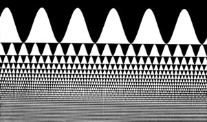
When smeared vertically this creates the sharp edged vertical bars of a square wave grating! This demonstrates the Fourier components of a square wave, with relative frequencies 1, 3, 5, 7, 9… and relative amplitudes 1/1, 1/3, 1/5, 1/7, 1/9….

A Craik-O’Brien-Cornsweet edge. The left and right regions have the same luminance but the spur-shaped luminance profile makes the right half look brighter.

Components of a Cornsweet edge are a sharp spatial step in luminance, which is very visible, plus a gradual spatial luminance ramp in the other direction, which is much less visible because the visual system is insensitive to low spatial frequencies.

How does a computer reconstitute X-ray slices to make a CAT scan? or MRI scan? Oscar Estevez (U of Amsterdam) shows this demonstration to his medical students: He rotates the cylindrical lens slowly in its own plane (around the axis of the projector beam). When the smear direction lines up with one edge of the triangle, a luminance edge appears in the smear. Smart students can guess from this that the target slide is a triangle. And a computer can guess that a target object is a brain.

Split Dots

Split Dots
With Hiro Ito

Magnified View of dot pairs. A pair of dots of different contrasts and polarities jump back and forth along orthogonal, crossing paths.

If the stimulus geometry were the only factor, all dot pairs would appear to jump along parallel paths. In fact, however, it is the vector summation of their different contrasts that make the dot pairs appear to follow different paths.

Continuous version of the split dots stimulus. All dot pairs are black & white. On the light surround at the left, they appear to drift UP to the right, and on the dark surround at the right, they appear to drift DOWN to the right.

Zebrafish

Zebrafish

with Michael Orger, Mattew Smear, and Herwig Baier (UCSF)

Zebrafish Larvae Respond to Second-Order Apparent Motion

A moving grating elicits innate optomotor behavior in zebrafish larvae; they swim in the direction of perceived motion. We took advantage of this behavior, using computer-animated displays, to determine what attributes of motion are extracted by the fish visual system. As in humans, first-order (luminance-defined or Fourier) signals dominated motion perception in fish; edges or other features had little or no effect when presented with these signals. Humans can see complex movements that lack first-order cues, an ability that is usually ascribed to higher-level processing in the visual cortex. Here we show that second-order (non-Fourier) motion displays induced optomotor behavior in zebrafish larvae, which do not have a cortex. We suggest that second-order motion is extracted early in the lower vertebrate visual pathway.

Ted Adelson’s apparent motion of a square wave minus its fundamental. Features (such as edges) move to the right but Fourier motion energy moves to the left. Result: Humans see motion to the left. So do zebrafish, responding to the Fourier motion energy, even though they have no cortex but only a primitive optic tectum.

[quicktime width=”500″ height=”300″]http://anstislab.ucsd.edu/files/2012/11/zebrafish3.mov[/quicktime]

In this second order stimulus the moving bars are defined only by texture, not by luminance; on each frame, every 8th column reverses in contrast. There is no rightward motion energy, yet zebrafish will swim along to follow this stimulus.